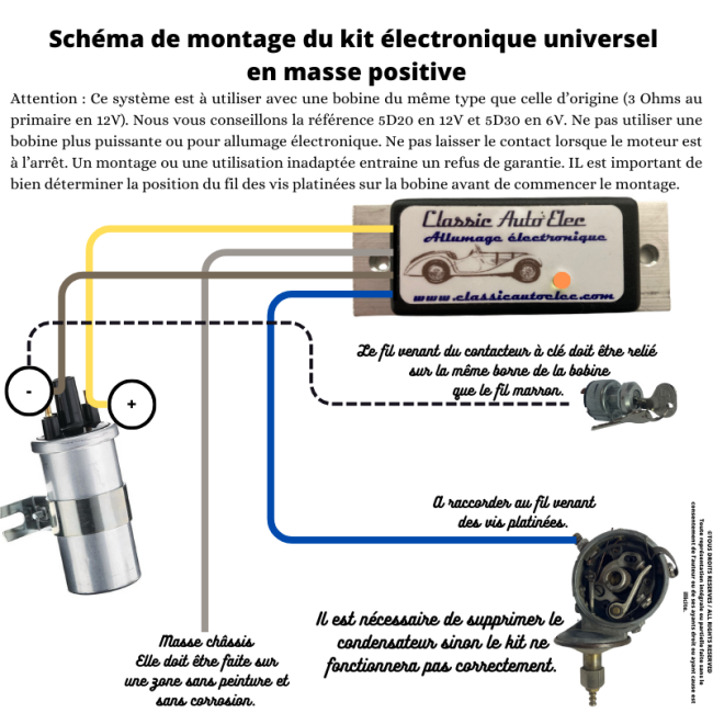


Free fitting diagram for the universal electronic ignition kit, positive earth, replacing the contact points.

Secure payment by credit card, Paypal, check or bank transfer

Delivery in 48 hours

Customer service at your disposal from 9 a.m. to 5 p.m.
This free diagram shows how to wire our universal electronic ignition kit on a positive earth vehicle.
This system must be used with a coil of the same type as the original (3 ohms primary in 12 V). We recommend part number 5D20 in 12 V and 5D30 in 6 V. Do not use a more powerful coil or a coil for electronic ignition. Do not leave the ignition on when the engine is stopped. Incorrect fitting or use will void the warranty. Before starting, make sure you identify which coil terminal the contact points wire is connected to.
Free fitting diagram for the universal electronic ignition kit, positive earth, replacing the contact points.