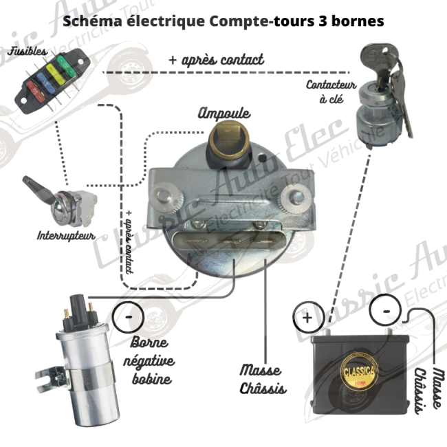


Free wiring diagram for a 3-terminal rev counter: ignition-switched +, coil –, earth and illumination.

Secure payment by credit card, Paypal, check or bank transfer

Delivery in 48 hours

Customer service at your disposal from 9 a.m. to 5 p.m.
The rev counter reads the pulses from the ignition coil to show engine speed. This free diagram shows how to wire a 3-terminal model.
Free wiring diagram for a 3-terminal rev counter: ignition-switched +, coil –, earth and illumination.