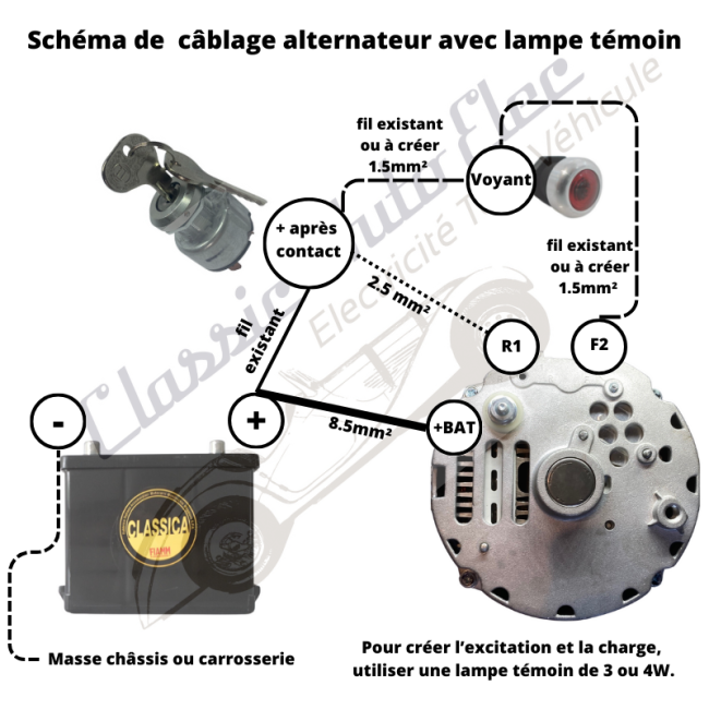


Free wiring diagram for an alternator with charge warning lamp: wire sizes, terminals to connect and the role of the warning light.

Secure payment by credit card, Paypal, check or bank transfer

Delivery in 48 hours

Customer service at your disposal from 9 a.m. to 5 p.m.
This free diagram shows how to wire an alternator with a charge warning light on the dashboard, for example when replacing a dynamo with an alternator on a classic car.
The warning lamp does more than warn you: it provides the alternator's excitation at start-up. Use a 3 or 4 W bulb. With a bulb that is too weak, the alternator may not start charging.
With the ignition on and the engine stopped, the light comes on. It should go out as soon as the engine runs and the alternator charges.
Free wiring diagram for an alternator with charge warning lamp: wire sizes, terminals to connect and the role of the warning light.